The Panasonic Motor Unit
Components, Operation and Repairs
Components, Operation and Repairs
Very few repairs are possible within this unit, partly because most faults are electronic ones affecting the sealed in mainboard, and partly because separate spares are usually not available. However, those that are known to be possible are explained within the following, and all internal assemblies are illustrated in fully broken down detail to enable repair and re-assembly anywhere it proves possible.
Essential tools for repairs to this unit are the usual tools required for stripping the motor cowlings and removal of the motor unit from the frame, plus a crank extractor tool, small circlip pliers, and an externally small 8 mm socket or tubular spanner.
Essential tools for repairs to this unit are the usual tools required for stripping the motor cowlings and removal of the motor unit from the frame, plus a crank extractor tool, small circlip pliers, and an externally small 8 mm socket or tubular spanner.
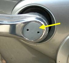
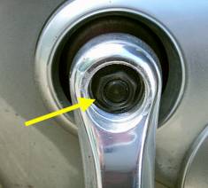
If you suspect a fault is something to do with the motor unit, you'll need to check each of the wiring connectors within the left hand cowling, so start by removing the crank plastic cap on the left and the nut shown at the right.
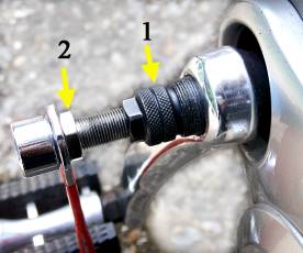
Then take your crank extractor tool, shown at the right, and unscrew the centre bolt (2) well out. Then screw the outer part (1) completely into the crank thread, taking care not to get it cross threaded. Once the outer is fully screwed home, tighten the centre bolt against the crank spindle end using the extractor handle or a spanner until the taper fit of the crank on the spindle releases. Then remove the extractor tool and the crank. Now remove it's screws and strip off the left hand cowling.
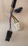
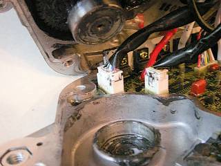
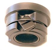
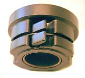
With the left hand cowling removed you'll see the black rubber grommet surrounding the cables emerging from the unit, and on those there are connectors as illustrated on the right, all of them not necessarily connecting to anything.
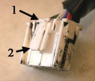
With those that are connected, unplug and re-plug them two or three times to ensure a sound connection. All the connectors in this unit are like the white connector shown below at the right. On the side blade, there is a catch at (2) which is released by pressing in or squeezing the top of the blade at (1). Then the connector can be parted. Once the connectors have been checked, temporarily replace the crank and check the bike's function for satisfactory working. If all is well, the cowling and crank can be reassembled.
With those that are connected, unplug and re-plug them two or three times to ensure a sound connection. All the connectors in this unit are like the white connector shown below at the right. On the side blade, there is a catch at (2) which is released by pressing in or squeezing the top of the blade at (1). Then the connector can be parted. Once the connectors have been checked, temporarily replace the crank and check the bike's function for satisfactory working. If all is well, the cowling and crank can be reassembled.
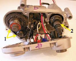
If the fault condition persists, you'll need to consider whether to fully strip the unit to check for faults, a major job requiring the unit's removal from the bike. If you decide to go ahead, first remove both cranks, then all the motor cowlings, disconnect the wiring connectors and unbolt the battery connector platform, both shown in the right hand illustration. Then undo the through bolts holding the motor unit to the bike frame and remove the unit to a bench.
Using your circlip pliers, remove the circlips that retain the 37 tooth chainwheel and 14 tooth motor sprocket onto their splined shafts. Then slide off both sprockets.
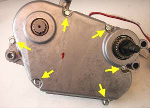
Now use your 8 mm tube or socket spanner to remove the six case bolts shown at the left and turn the unit to look at the left hand side. At the left and right extremes you'll see two points where the R/H case overlaps the L/H case. Hold the case up by the black motor casing and use a hammer to firmly strike each overlap in turn to break the joint seal.
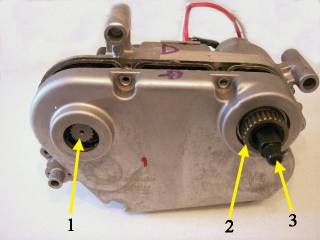
With the case halves beginning to part, jiggle the R/H one outwards, keeping the spindles at (1) and (3) pushed back into the unit, but allowing the splined outer at (2) to come out with the right hand case side.
You'll now have this view at the left of the unit's internals, the shaft ballrace bearings at (1) and the needle roller bearing at (2) on their shafts. The needle roller cage can slip off with the case side but is easily put back on. The right and left hand areas are coated with black graphite or lithium grease, so rather messy to touch.
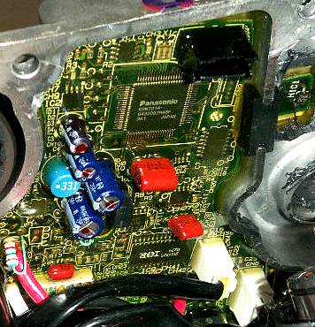
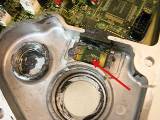
The main circuit board is shown here, and since this is fully encapsulated in silicone rubber and sealed into the right hand case side, there are no serviceable parts and board replacement isn't really possible.
The large black square component with mutiple connections and bearing the Panasonic name is the central processing unit (cpu) which computes the motor's behaviour from the sensor inputs. At the extreme right, the black component marked HIC1 is the Hall sensor which reads the chain sprocket speed, about which more later. At the lower right are two white cable connectors which you'll see again below.
The large black square component with mutiple connections and bearing the Panasonic name is the central processing unit (cpu) which computes the motor's behaviour from the sensor inputs. At the extreme right, the black component marked HIC1 is the Hall sensor which reads the chain sprocket speed, about which more later. At the lower right are two white cable connectors which you'll see again below.
Here's those connectors again, unplug and replug the smaller one on the right here several times to ensure a sound connection.
Then unplug the larger one and leave it unplugged since we now need the cable from it left slack for the moment.
Then unplug the larger one and leave it unplugged since we now need the cable from it left slack for the moment.
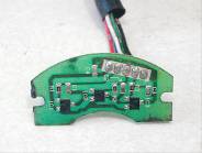
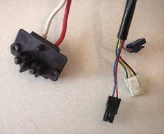
That cable goes out through a hole in the L/H casing to the Hall sensor board shown on the right. This sits against the side of the motor and reads it's magnetic states during operation, feeding the information to the cpu on the mainboard. Panasonic didn't design the boards mountings well and it can come adrift easily, creating faults, and we've left it's cable slack so as not to pull it off it's mountings before the next checking stage.
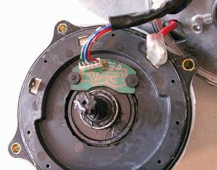
Here I've detached the motor unit completely from the L/H casing to show the Hall sensor board in it's correct position on the motor side, located by two plastic pegs formed into the motor case, with two rubber washers pushed onto the pegs to hold the board in place. With the warm motor's greasy gear shaft alongside, a film of grease easily deposits around the washers making it easy for them to slip off. Bad design, Panasonic. It's displacement of this board which causes malfunction that we now need to check for.
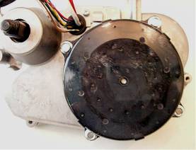
This is the left hand external view of the black plastic motor casing with it's four 8 mm fixing bolts, similar to the right hand case bolts but longer
Remove the four motor mounting bolts you saw above, then give sharp taps on the bolt lugs of the motor casing to break it's seal to the left hand alloy casing. With the seal broken, carefully withdraw the motor about a quarter inch or so, ensuring the cable to the hall sensor board does not snag in the alloy case and pull the board off. Then peer through the gap using a torch if necessary to ensure the board is correctly located on the lugs with the rubber washers in place.
If it was adrift and you're sure you didn't disturb it, that may have been the cause of the bike's fault. In that case, prise off the three push on connectors (fast-ons) of the main current supply to the motor, noting the colour coded positions in writing, then withdraw the motor as I've shown it above, where I still have the red lead connected to it's fast-on tag.
Now use a solvent like meths or Iso-propyl alcohol to thoroughly degrease the pegs and washers. Then refit the board as shown above, but using a touch of glue on the washers and pegs ends to keep them in place. With the glue set, refit and bolt the motor, passing the Hall sensor lead through the alloy casing wall, then plug the faston connectors back onto the motor in their correct positions. Make sure they are pushed firmly over the metal tags, and not just the tags sitting between the outer connector and the plastic insulator. Now plug the large connector from the Hall sensor board back onto the mainboard.
The only remaining repair normally possible within the motor unit is bearing replacement, and since the only failed bearing known of to date was a motor one, it's failure indicated by squealing sounds, we'll stay in the motor area at present.
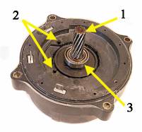
So here's the motor again, this time with Hall sensor board off showing the plastic locating pegs at (2), the motor shaft at (1) with the helical gear cut into the shaft, and at three it's inboard bearing. This bearing is small but has the toughest job of all in this unit. It runs faster than the others, and in addition to it's normal radial loads, it has to carry the axial thrust due to the helical drive. All these bearings are standard ball race types obtainable from bearing suppliers everywhere.
Checking connection soundness externally and internally, refitting a displaced Hall sensor board and replacing a bearing are all the known possible repairs to this Panasonic motor unit, but now we can go onto all the other sub areas of the unit, showing the items, their functions and the assembly details so that it can be ascertained whether a unit is in correct condition for working properly.
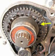
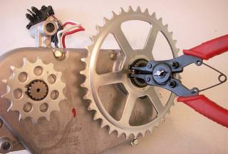
On the left is the motor sprocket shaft and it's large gearwheel and bearing, and the arrow points to one of a ring of 24 magnets. These are read by the red arrowed Hall sensor on the right which sits next to the bearing housing in the opposite
casing. This sensor mounting is an extension of the mainboard and it feeds back the sprocket and thus chain speed to the cpu.
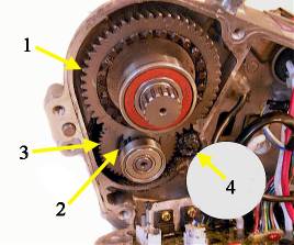
While in the gears area, here is a partially cleaned up helical geartrain. The shaft that holds the output chain sprocket has the large gearwheel (1) on it, and this engages with the small gearwheel (2). Gearwheel (3) has a freewheel centre, so when pedalling without motor drive, only gearwheels (1) and (2) turn, gearwheel (3) and the motor shaft (4) remain still and don't provide drag. When the motor runs, the shaft (4) turns anti-clockwise, (3) and (2) turn clockwise against the freewheel, so (1) turns anti-clockwise to drive the chain over the sprocket as it leaves the chainwheel.
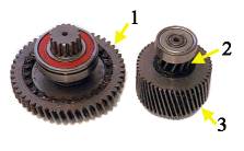
And here's the gears numbered to correspond with the illustration above, stripped out and cleaned to show the details. The way gearwheel (2) forms the inner part of the freewheel assembly inside gearwheel (3) can also be seen. Very rarely this freewheel can jam on, the details to carry out a repair are on this link
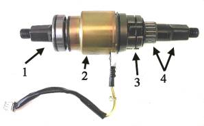
Here's the pedal shaft assembly withdrawn from the left hand case. At (1) is the L/H crank taper and bearing, and at (2) the pedelec sensor drum. At (3) is the pawl assembly of the pedal shaft freewheel, which allows freewheeling while the motor overruns slightly to avoid drive snatch, and at (4) are the needle roller cage and R/H crank taper. The cable from the pedelec drum has the small white plug that connects into the mainboard.
And this is the other part of the pedal shaft freewheel that we left in the R/H case when we pulled the case halves apart. On the left you see the chainwheel splines and the case bearing that permits independent rotation, and inside there's the bearing race for the needle rollers. At the outer edge of both roller and needle bearings are neoprene seal rings to prevent grease leakage.
And this is the other part of the pedal shaft freewheel that we left in the R/H case when we pulled the case halves apart. On the left you see the chainwheel splines and the case bearing that permits independent rotation, and inside there's the bearing race for the needle rollers. At the outer edge of both roller and needle bearings are neoprene seal rings to prevent grease leakage.
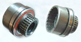
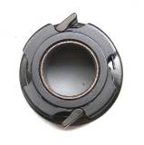
On the right you see the view into the freewheel pawl toothed ring which sits completely over (3) on the pedalshaft in the illustration above to give the freewheel facility.
There should be no need to strip it, but here's the pedalshaft assembly stripped to show its components. The pedelec drum insert sleeve engages with the splines on the L/H shaft and the splines in the freewheel assembly.
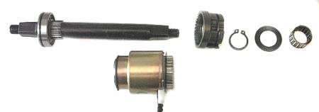
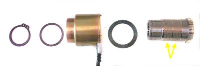
This is the pedelec assembly shown below the spindle in the illustration above, here stripped to show the drum and it's inner sleeve. Note the arrowed cross hatched roughened stripes on the sleeve that give rotation sensing.
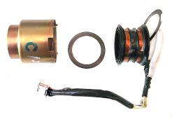
The pedelec drum is a sealed assembly, but for completeness I've broken it apart to show it's inner workings. Inside the drum is this centre tapped twin coil winding, it's three wires going to the small white connector. The windings sit over the two hatched zones of the inner metal sleeve arrowed above. Since the sleeve turns with the pedal shaft, the raised metal areas of the hatching disturb the magnetic field generated by the coils, thus indicating rotation by feedback of the disturbance. As
the bike is pedalled without power, the drive to the pedelec sleeve is from the shaft splines, loaded against the pedalshaft freewheel driving the chainwheel. This imparts a left driven twisting/warping motion to the sleeve, giving a minute differential to the left hand and right hand disturbance of the two coils magnetic fields. In contrast, when the motor is running full on and pedal thrust is minimal, the twisting motion doesn't exist since the load of the pedalshaft freewheel is removed and the sleeve is free to spin, and therefore the magnetic fields are equalised. Between these two are an infinitely variable set of states which can be read by the cpu in setting the motor contribution to the drive needs. Thus the pedelec sensor acts like a strain gauge to sense rider effort as well as rotation.
In partnership with this, the Hall sensor that is an extension of the mainboard is reading the 24 magnets on the gearwheel of the unit's chain sprocket shaft, and is therefore detecting rotation speed, indicating road speed in top gear to enable the cpu to phase down power at around 13 mph and cut it at the 15 mph legal limit. On a 3 speed Twist at 13 mph, the magnets pass the Hall sensor at a rate of just over 77 per second, therefore giving more than enough feedback to give a very high degree of road speed accuracy. That same magnet gearwheel is also the output drive from the motor when that is operating. Since the only drive connection between the pedalshaft drive and the output shaft is the chain, tensioned by a spring loaded idler, variations in the contributions from each can be sensed as tiny changes in relative speeds of the two, this again probably assisting the cpu in managing the motor behaviour. The net result is a motor control system that is superior to any other yet in pedelec bikes, somewhat bionic in it's nature as it responds to rider input by adding power to the muscle power on pedal strokes.
In partnership with this, the Hall sensor that is an extension of the mainboard is reading the 24 magnets on the gearwheel of the unit's chain sprocket shaft, and is therefore detecting rotation speed, indicating road speed in top gear to enable the cpu to phase down power at around 13 mph and cut it at the 15 mph legal limit. On a 3 speed Twist at 13 mph, the magnets pass the Hall sensor at a rate of just over 77 per second, therefore giving more than enough feedback to give a very high degree of road speed accuracy. That same magnet gearwheel is also the output drive from the motor when that is operating. Since the only drive connection between the pedalshaft drive and the output shaft is the chain, tensioned by a spring loaded idler, variations in the contributions from each can be sensed as tiny changes in relative speeds of the two, this again probably assisting the cpu in managing the motor behaviour. The net result is a motor control system that is superior to any other yet in pedelec bikes, somewhat bionic in it's nature as it responds to rider input by adding power to the muscle power on pedal strokes.
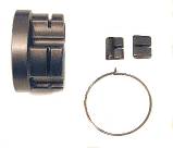
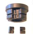
The pedalshaft freewheel pawl assembly shown at the right can be accidentally disassembled when opening up the motor. The remaining illustrations show the details and reassembly. The first illustration below shows the parts, with the L/H pawl shown upside down to illustrate the difference. Next there's the wire circlip in place with ends showing. This position and the one opposite are not used for pawls. The other two positions are for the pawls, the third illustration showing one being loaded into place. Then with the pawl located, the circlip spring action holds it in the operating position.
Now you've seen all of the internal components and sub assembly details, maintenance like greasing can be undertaken when necessary. I would always recommend you wait until noise indicates any dry parts though, since these units are very heavily greased and well sealed so are unlikely to need maintenance during the working lives of most bikes.
After any repairs or maintenance involving parting the crankcases or the motor from the L/H crankcase, the joint should be resealed when assembling. For this it's probably easiest to follow Panasonic's example and use silicone rubber sealant as it's readily avalable from DIY stores.
I hope this page will be helpful in understanding this unit and assisting with any repairs and maintenance that are possible. Please take note of the disclaimer on the home page, since these are complex units and you should be aware of your own limitations when attempting any repairs. I always appreciate feedback of any experiences of fault conditions on this unit, for which you can use the contact button on the home page.
14.8.2007
.
.
Electrical information
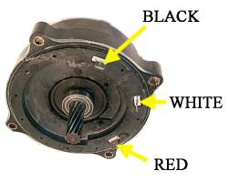
At the right the motor is seen in it's normal orientation with the cable connection colours for the fast-on tags indicated. To check the motor windings for continuity, you can use a test meter, buzzer or test lamp. First unplug the cables. Then using the cable colour references that I've given the tags check between each pair of motor tags, black to white, white to red, and red to black. Each pair tested should have continuity and zero resistance on a test meter, or full bulb brightness.
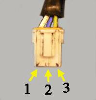
This illustration shows the pedelec drum connector. Number 3 is the common connection to the centre tap between the two pedelec sensor coil windings, numbers 1 and 2 being each coil. Between both 1 and 3 pair and 2 and 3 pair there should be continuity and approximately 78 Ohms resistance in each coil. To make these measurements, the easiest way to access the connections is to insert a tailors/dressmaking pin into each position which you can connect your probes to.