The eZee Lithium Ion Battery
A gallery of photographs and description of the original eZee Li-ion battery internals, later types somewhat different but the principles the same as here.
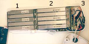
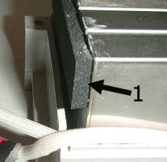
Here at the right is the overview of the open battery showing (1) the lower bank of five cells and (2) the upper bank. At (3) is seen the main current control area.
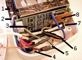
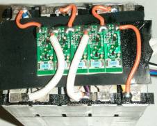
On the left is a close up of the main current control area at the top of the battery casing. At (1) is the connector for the control wires of the lower bank of cells, at (2) the current control wires for the upper bank via the connector at (5). The main control circuit board is at (3), all the wires from (1) and (5) leading to it's white connector at the left. An internal fuse (6) is in series with the external fuse (4), as a protection against anyone fitting an oversize fuse.
Number (7) points to a plastic spacer block that limits the upward float of the cell packs within their suspension. If you've ever wondered what it is that rattles loose inside the battery, it's this block, left floating so that it doesn't cause damage to the upper cell pack as that shifts in the casing. Then number (8) points to the copper heat sink for the two semi-conductors beneath it. The tiny components you see on the board are surface mount types, making it a disposable circuit board, not easily repairable but generally very reliable anyway.
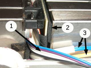
At the right is a view of the area between the lower bank of cells at the left and the upper bank at the right. (1) points to the five control leads from the lower five cells, with (3) being the power leads from those cells. Number (2) is the foam rubber support and suspension pad which cushions the weight of the upper cell bank.
And here's the suspension for the lower cells.
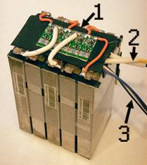
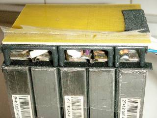
This is one complete cell bank assembly, capped by the monitor circuit boards at (1), with the power output leads (2), and the current control leads (3). Each cell weighs approximately 360 grams.
And here's a close up of those printed circuits, five in all, giving individual monitoring of each cell. Again these are populated with miniature surface mount components, meaning repair isn't practical, but these components are very reliable anyway.
This shows the support arches and insulation capping panel that sits above the lower cell pack, carrying the weight of the upper pack via it's foam rubber suspension pads.
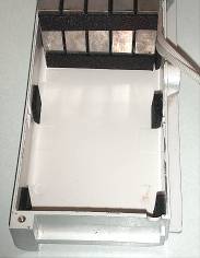
And finally the suspension pads that surround each cell pack, here the lower set is shown. Note the threaded hole brass insert for the case securing screw at the lower left, also seen on the securing post in the second photograph above. This sort of case is commonly assembled using self tapping screws into the plastic, so it's reassuring to see this component quality and attention to detail.
24.3.2009
.