Q Bike Creation & Performance
You will have gathered from the preamble that the aim of this conversion was to maximise the efficiency of the final bike. The first and most essential thing was to add gears, which with a rear motor means a freewheel based derailleur system, but the problems with that were huge. The motor is very wide, far wider than those intended for rear wheel with gears, made worse by it having an integrated left hand steel drum for the band brake that was formerly fitted. It had a BMX freewheel thread for which no multi-sprocket freewheels are made, and the threads difference is only 2.5 mm around the circumference which would have to have internal and external threads cut into it, hence no after market adapters.
If the motor could be modified and offset sufficiently, the rim would be severely out of line with the V brake fitted. Worse still, the spindle, hollow for the cables, is not strong enough to have outboard support for multi-sprocket freewheel space. The rear frame aperture, though wide was still much too narrow, and even if widened, the sharp outward angle of short tubes for the 20" wheel meant that a multi-sprocket freewheel could not enter the forward facing conventional spindle slots. Somewhere a start had to made to overcome these problems though, so caution was thrown to the wind.
If the motor could be modified and offset sufficiently, the rim would be severely out of line with the V brake fitted. Worse still, the spindle, hollow for the cables, is not strong enough to have outboard support for multi-sprocket freewheel space. The rear frame aperture, though wide was still much too narrow, and even if widened, the sharp outward angle of short tubes for the 20" wheel meant that a multi-sprocket freewheel could not enter the forward facing conventional spindle slots. Somewhere a start had to made to overcome these problems though, so caution was thrown to the wind.


At the right you see the bandbrake drum arrowed, covered with it's rust protective coating as it's not now used in today's models, and with the motor components stripped out, bearings removed and the hub interior sealed. The second photo shows the outcome after attacking it with an angle grinder and refitting the bearing, narrowing the hub for freewheel width.

Unfortunately after they'd accepted the job, they obviously had regrets and messed me about for weeks before finally managing it sufficiently well, though I had to modify it later in my lathe. The other solution was to cut behind the spoke flange of the full thread end of a DMR Revolver alloy hub, turn it to fit and weld it to the motor side which I could do completely myself, but by adopting the route I took I had both options available, where cutting off the existing thread at the beginning would leave me only one.
Below is the undersize freewheel thread and the hollow spindle, which also had top and bottom flatted for the dropouts. With a wide sprocket set and the spindle supported outboard, the first pothole struck would probably snap the thinwall spindle like a carrot. But first to tackle the thread problem for which I had two possible solutions. The obvious choice was to make a threaded adapter despite the difficulty, but my lathe has no threading attachment so this was the one job I had to use an engineering company for.


If you look at the photo above again, you'll see the spindle has a thicker and much stronger section inboard next to the freewheel thread. My simple solution to the weak spindle was to turn an adapter sleeve so that it was a press fit over that and could carry most of the spindle vertical loading out to the thick and strong Quando frame dropout slot and clamped there by the wheelnut. At the right you can see the sleeve, the press fit recess at the top, the spindle hole below, and with most of it's body length turned to 22 mm to fit snugly inside the splined sleeve of a multi sprocket freewheel.
By making it a snug fit in that way, if an excess impact loading does tend to bend the spindle the sleeve will momentarily contact the inner of the freewheel, transmitting the loading inboard and sharing it with the freewheel's threaded boss, preventing spindle failure. The fitted sleeve can be seen at the right without the freewheel in place. Since this photo I've reduced the sleeve length slightly and added a half nut to clamp it internally within the frame, and added removal slots so the sleeve can be prised out for freewheel replacement anytime.

Time for the first choice of derailleur components. The freewheel finally chosen is seen fitted at the right on it's thread adapter, sleeve in place and half nut clamping it, the large clamping faces to protect the spindle via frame strength evident. Also clear to see is the very small clearance from the sleeve body to the freewheel spines giving the emergency support in cases of an extreme impact situation.
There were four freewheels available, one 14 to 24 tooth 7 speed close ratio useless for electric bikes, leaving three, a 14 to 24 tooth 5 speed, the 179%
There were four freewheels available, one 14 to 24 tooth 7 speed close ratio useless for electric bikes, leaving three, a 14 to 24 tooth 5 speed, the 179%
range inadequate, a 13 to 34 tooth megarange 6 speed with good 262% range, and a better quality 11 to 34 tooth megarange 7 speed with 309% range. Of those latter two suitable ones, it had to be the 6 speed for several reasons. Bearing in mind my ruthless pursuit of efficiency, the tight chain turn around an 11 tooth is inefficient. Tiny sprockets like that 11 tooth wear very fast, necessitating scrapping the whole freewheel at �19.99, (the chosen one being only �9.99). And third, these multi-sprocket freewheels are much weaker than cassette systems due to them only having inboard bearings. The further out the chainline goes, the greater the strain and lower the reliability. That seventh gear 11 tooth was a step too far, and an electric bike doesn't need lots of gears anyway, due to the motor's ratio-gap bridging power. An adequate range is the only thing that's needed.

Good progress so far, but there was still the matter of the wheelrim being offset for the V brake once the frame was widened enough to accommodate it. The solution had to be the conventional one of rebuilding the wheel with an offset. This is ok for a small hub in a large rim as with that for normal derailleur accommodation, but with a 5.5" diameter hub in a 20" rim, the very short spoke's angles were going to be extreme and the near vertical inner spokes under relatively high tension to maintain the consistency of the build. The extreme offset is seen at the right, certainly the most difficult build I've ever done, but it's worked and after weeks of hammering on rough local lanes and plenty of load carrying and towing all is well.

Now it was time to get brutal again, this time with the frame. The faint hearted should look away now! The rear frame had to be expanded to a minimum of 175 mm at the dropouts, with a shape change to follow. In the absence of a custom stretcher I used the inside element of a puller with it's arms removed, and this you can see in use at the right. By a steady process of selectively repositioning and expanding, the desired initial spread was reached while monitoring the frame tubes closely. This was deliberately done with all the associated elements still in place, towbar, mudguards etc to get those adjusted as well.
Next the frame tubes had to be reshaped to bring the dropout plates back into parallel and leave entry space for the multi- sprocket freewheel entry. To complete this it was necessary during the process to cut and separate two frame welds, the mudguard support tube R/H join and the stand bearer R/H join.
These I re-welded later, but both were non critical. The former is duplicated by the battery holder support tube, and the stand plate would no longer be in use since it was incompatible with the chain path. The shaping was done as shown, by clamping at the dropouts and expansion in between until a suitable profile was reached with parallel dropouts.


The photo on the right shows the curvature of the rear frame tubes achieved. Follow the upper tube upwards to alongside the mudguard and you can see the re-welded tube and the strengthening web following the mudguard curvature that I welded across the lower inner of the join. Here the bike is part reassembled but the old stand is still fitted for working stability convenience. Refinishing after welding was done with a power wirebrush followed with a clear lacquer spray left to harden for days.


Now it was time to complete the rear derailleur, for which I first had to get the part shown at the right, Shimano's general purpose gear hanger for the rear mechanism attachment. This proved difficult to get hold of, dealers not unreasonably feeling that if you want a derailleur bike, you should buy one, not convert the old roadster at the back of the garage, making this an unpopular item, though I eventually found a source for it.
The choice of rear mechanism wasn't difficult as I wasn't exactly spoilt for choice of suitably efficient models. The requirements were that it had to be suitable for a small wheel, and it had to be megarange compatible, able to span to that big 34 tooth sprocket. When a megarange is used, the angular movement range of the rear mechanism is large, leaving roughly the position shown at the right when in top gear. This of course means tight chain turns which are inefficient. The way to alleviate this is to have larger jockey wheels, so one mechanism stood
out, Shimano's Acera smart cage. This uses exceptionally large jockey wheels as you can see, 13 and 15 tooth, minimising the efficiency losses, and is both megarange compatible and suited for small wheel use. It's at a mid range price too which helped.
A quick diversion now on the subject of the megarange sprocket sets. These are widely and in my view justifiably criticised by keen cyclists for their extreme gearing step and the cadence inefficiency that results. The position for electric bikes is radically different though. Here the possession of a very low separate gear is perfect as a "get me home" for pedalling a heavy e-bike if the battery runs out. That low gear is still useful on an e-bike anyway, since having a constant motor power source supplementing pedalling provides a gear-gap power bridge, filling in until pedal cadence returns to suitability.
A quick diversion now on the subject of the megarange sprocket sets. These are widely and in my view justifiably criticised by keen cyclists for their extreme gearing step and the cadence inefficiency that results. The position for electric bikes is radically different though. Here the possession of a very low separate gear is perfect as a "get me home" for pedalling a heavy e-bike if the battery runs out. That low gear is still useful on an e-bike anyway, since having a constant motor power source supplementing pedalling provides a gear-gap power bridge, filling in until pedal cadence returns to suitability.
The transmission could now be completed, the chainring size having already been chosen to go with the selected freewheel, and it's this monster 60 tooth one you see at the right below. A big chainwheel is necessary on a small wheel bike to get an adequate gear range of course, and large diameter chainwheels are efficient anyway so suiting my objectives. This gives me a gear range perfectly matched to the bike's motor gearing, it's intended uses and performance, the gears being 35", 50", 57", 67", 80", 92". The 67" to 92" gears are those routinely used in day to day cycling, the 57" only coming into play
with heavy loads or the trailer on fairly steep hills. The 35" and 50" are both "get me homes" for flat battery situations and also for handling the most extreme climbs steeper than 1 in 6 (18%). The chainline has been optimised for the three most commonly used and high gears to give the highest overall utility of the available efficiency, not the usual averaging for all gears. This is because there's plenty of ability for low speed uses, but motor legal limiting means all higher speeds have to come from me so I want optimised conditions. The gear range specified
means that I have a comfortable pedalling range from 4.2 mph at a 40 cadence in low gear, which would enable a much steeper than 1 in 4 (25%) hill, and in top gear, 24.8 mph at the generally accepted physiological optimum of a 90 cadence. The maximum I can manage, a 100 cadence, gives 27.6 mph, speed over that courtesy of gravity downhill.
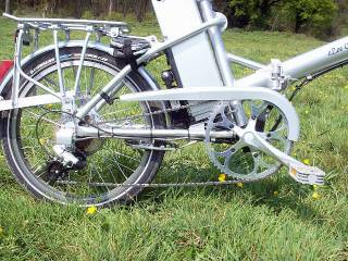
The Quando originally has short 152 mm cranks, ground clearance for novice cyclists instead of the standard of around 170 mm, but I've installed 160 mm pedal threads in new cranks as a compromise that suits my pedal cadence preferences and gives adequate ground clearance for me. You will have noticed that very unusually, this derailleur bike has a chainguard. And why not? I was determined that I wouldn't lose any of the Quando's abilities, and those included it being a handy hop on and off utility bike, the sort you pop down to the shop with, not bothering about special clothing or cycle clips. With a trouser leg never able to reach the bottom of that large chainwheel, only the top run protection was needed. The Quando has a full front chainguard covering the whole 48 tooth chainwheel which obviously couldn't fit, but I cut and styled the one you see from that, the "Nike tick" motif being echoed by the car-style tow-hitch, my one styling gimmick, a sort of "go faster" stripe. The front two mounting brackets are made from high tensile chromed steel strip salvaged from the council recycling depot metals skip, then finished with hard clear lacquer as a rust preventative. The pedelec sensor stays in place and is fully functional.
The Quando originally has short 152 mm cranks, ground clearance for novice cyclists instead of the standard of around 170 mm, but I've installed 160 mm pedal threads in new cranks as a compromise that suits my pedal cadence preferences and gives adequate ground clearance for me. You will have noticed that very unusually, this derailleur bike has a chainguard. And why not? I was determined that I wouldn't lose any of the Quando's abilities, and those included it being a handy hop on and off utility bike, the sort you pop down to the shop with, not bothering about special clothing or cycle clips. With a trouser leg never able to reach the bottom of that large chainwheel, only the top run protection was needed. The Quando has a full front chainguard covering the whole 48 tooth chainwheel which obviously couldn't fit, but I cut and styled the one you see from that, the "Nike tick" motif being echoed by the car-style tow-hitch, my one styling gimmick, a sort of "go faster" stripe. The front two mounting brackets are made from high tensile chromed steel strip salvaged from the council recycling depot metals skip, then finished with hard clear lacquer as a rust preventative. The pedelec sensor stays in place and is fully functional.
Time now to greatly improve the efficiency of the other bike parts. Next
11.5.2007
.
.